
Making a compact dipole for 40 metre operation
Many HF antenna designs require physical length to achieve resonances at the lower frequencies. This is not always possible in all situations due to the space available.
However, there is a way to reduce the overall length of an HF dipole through the use of loading coils. Adding inductors to your dipole makes it possible to reduce the overall length of the antenna. The loaded dipole opens up the options for many armature radio users faced with space constraints.
Below is one example of how to build and mount a 40 meter loaded dipole using basic materials.
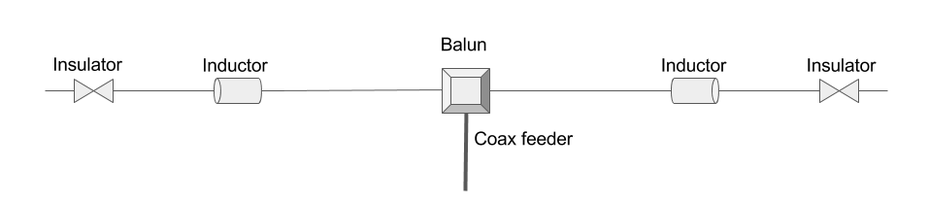
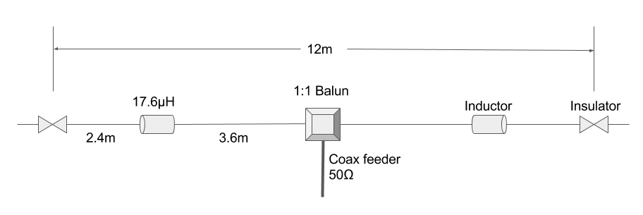
40 metre loaded dipole design
To design the dipole I used the fantastic Antenna design page created by Martin. E. Meserve: http://www.k7mem.com/Ant_Short_Dipole.html
I needed my dipole design to be 12 metres long and resonate on 40 mertre, the following design was generated:
- Inductance: 17.6mH
- Length A: 3.6 metres
- Length B: 2.4 metres
The coil design
The calculator provided on the Martin. E. Meserve website gave me the basic coil design parameters. I had some 50mm (outside diameter) plastic pipe and 2mm poly-weave wire, from this I had to work out the number of turns per inch. I did this by marking one inch on the pipe and winding some of the wire and counting the turns. I entered the details into the calculator which then gave me the number of turns and coil length required to achieve the required inductance:
Input parameters
- Inductance required:17.6 µH
- Wire diameter: 2mm
- Turns per inch: 12.5
Output parameters
- Turns per inch:11.2
- Turns needed: 22
- Length of coil:49.8mm
Making the coils
To construct the coils I marked out the width of the winding and the location of the terminal holes using a metalwork scribe. Two M4 terminal bolts were fitted, a ring terminal was crimped to one end of the cable to be used for the winding. The ring terminal was fastened to the terminal bolt, and the cable wound tightly around the pipe. When the desired number of turns was achieved, the cable was cut and the second ring terminal fitted and fastened to the remaining terminal bolt. The winding was tidied up, and super glue used to hold things in place.
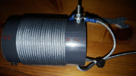
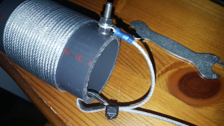
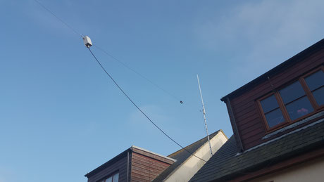
A cord grip was constructed by drilling two holes in the pipe and inserting a 4mm cleat into each hole (purchased from ebay). The antenna cable was then threaded through the cleat and secured with a nylon tie-rap as shown in the image above.
The antenna was constructed on the ground as per the dimensions shown. The ends were terminated by threading the cable through a 'dog bone' insulator and securing with a cable tie. I left about 200mm of extra cable folded over on the ends to aid tuning, just in case I got something wrong. All of the extra cable was to be later removed during tuning, bringing the antenna back to its original design lengths.
Once everything was connected up, I sprayed all of the connectors and joints with automotive lacquer to help protect them from corrosion.

Mounting the dipole
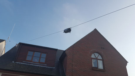
The dipole was attached between my 2M mast (which is bolted to the side of the house), the other to a corner fence post at the end of the garden. A pulley had been previously fitted to the mast, this made things a lot easier.
I did note that the balun and coils added some weight to the antenna, weight saving ideas would need to be considered for future designs!
Tuning
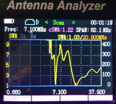
Some tuning was needed, the extra lengths I added during construction had to be trimmed off. Using an antenna analyser a low SWR was seen at 7.10mhz and 20.10mhz, other bands would also be fine with the use of an antenna tuner. During testing, using an ALD ATU, the antenna tuned in to 40m, 20m, 17m, 15m,12M and 10m! Good news!
Longer version
Once the antenna was up I could see that there was room to make a longer version. Again, by using the Antenna design page created by Martin. E. Meserve: http://www.k7mem.com/Ant_Short_Dipole.html I was able to create an improved design and add in the extra wire lengths. This change offered some improvement and broadened the usable frequencies of the antenna.
40 metre loaded dipole summary
This was an enjoyable project which offered big rewards for my efforts. The performance is okay, although you can see the SWR changes noticeably over the 40 metre band when tuning away from 7.1MHz. Weight is an issue and I am worried about the tension put on my mast mount, maybe a guy rope will help? Overall I am very happy, the antenna works and fits into my back garden.
See my trapped dipole page for the best solution for my modest back-garden :-)
Return to the QSO Shack Homepage.