
Make a 100 Watt linear amplifier from a kit
Many QRP rigs are capable of 5 or 10 watts of power, this is often enough for data mode DX, but sometimes you just need more punch to get heard on SSB. This page will show you how to build your own 100 Watt linear amplifier based on the kits that can be found on the various internet auction sites.
I initially tried making a 45 Watt amplifier kit but could not get this working (or find anybody else that had managed to get one working!). So I decided to try the 100 Watt amplifier kit. I found this 100 Watt amplifier to be of a much higher standard than the 45 Watt kit, There are also lots of references to the 100 watt kits on the internet. Therefore, this was the kit chosen to support this linear amplifier build project.

Concept
These amplifier kits are relatively cheap and are quite common on the internet. They can't be used as they are, a low pass filter and other items will also be needed to make this a practical piece of radio equipment.
This project will utilize a standard 100 Watt linear amplifier kit, a low pass filter, and other ancillary items to make a usable, boxed linear amplifier to suit a 5W QRP rig.
There are issues with this project, there is no high SWR, overheating, reverse polarity or other protection mechanisms built in. So it needs to be used with care. It's not going to be as refined as a purchased professional kit like the HardRock 50 or the Juma PA 100 kits. But it should be fun to build and certainly less expensive.
Parts and tools required
Most of the parts needed to build this amplifier are available from the normal online auction sites. Cost is around $100.
Main parts:
- 100 Watt amp kit
- Low pass filter assembly
- Heat sink (200W) at least 15cm x 6cm (bigger than shown in some of my photos)
Minor parts:
- STSP toggle switch 10-20 Amp
- Phono socket (chassis mount)
- 2x PL259 sockets (chassis mount)
- 3 mm twin gland nut
- Chassis mount LED (red) TX
- Rotary switch SPx4
- Metal enclosure
- M3 bolts
- Thermal path grease
Wire:
- 20 amp wire (red and black)
- 500mA wire
- Heat shrink
- 50 ohm coax
Tools:
- Soldering iron
- Solder
- Multi-meter with diode test function
- Oscilloscope with signal generator
- ESD protective mat and strap etc.
- 2.5 mm drill bits, M3 taps.
- Cutters and pliers
- Screwdriver
- Mobile phone with a camera, magnifying glass or great eyesight.


Low pass filter, why?
Along with the wanted frequency, the amplifier can also produce other frequencies due to harmonics. These unwanted frequencies can cause out-of-band interference which is obviously undesirable. A low pass filter will attenuate these unwanted frequencies down to a negligible level. The LPF is an essential piece of kit for any HF amplifier and has to be used.
For this project, we have chosen a four-band LPF. A rotary switch is used to select the desired operating band, the selected band is shown via an LED indicator.
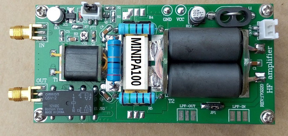
About the amplifier kit
My kit came with all of the fiddly SMT devices pre-fitted. No instructions were included, but the remaining parts were pretty straightforward to identify. The kit arrived boxed and all the parts appeared new and to a high standard, the mosfet device may have been a reclaimed part (used in the past).
You could save yourself the bother of building the amplifier for a little bit more costs. Built and tested amplifier boards are available. You'll still need to connect it up and add the LPF. So there is not much time to be saved with this option.
Build the 100 Watt amplifier board
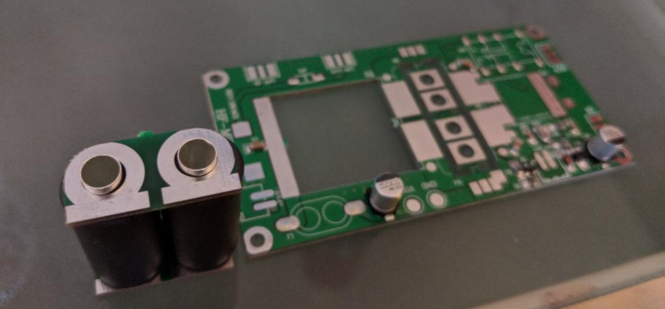
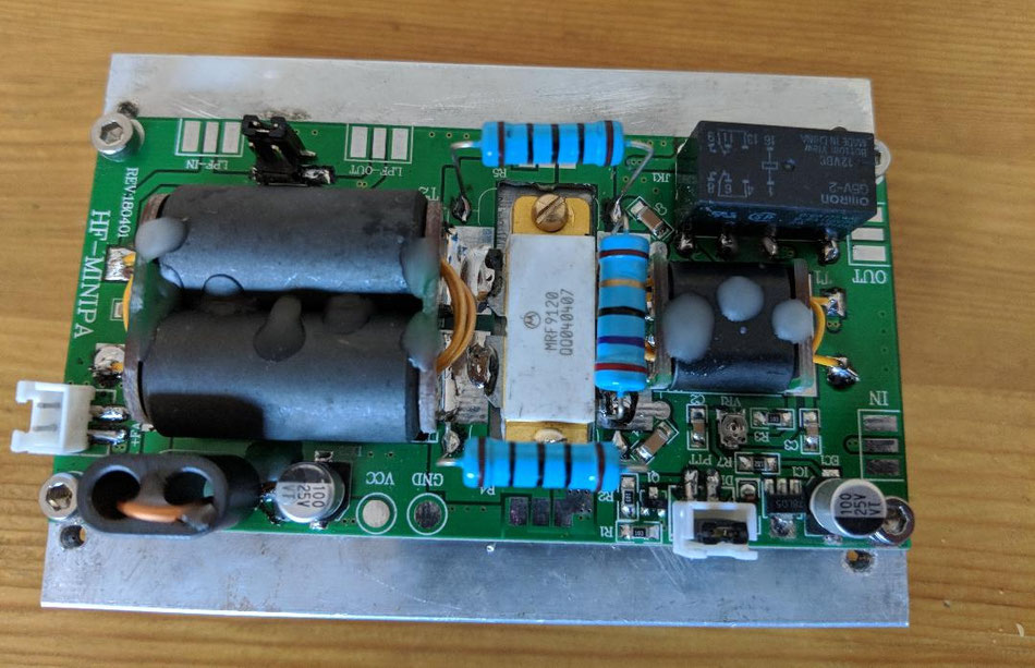
You'll need to refer to the 100 Watt amplifier images when making this kit. This will help identify components and how to make up the indutors etc..
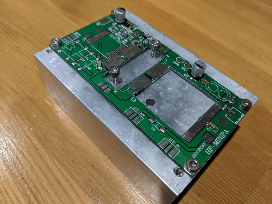
Drill and tap the heat sink
- Break out the inductor end plates from the PCB. You may want to file off any burrs. Place to one side.
- Lay the PCB on the heat sink. Lay the mosfet device on the PCB.
- Mark the PCB mounting holes with a pen. Mark the Mosfet mouting holes as well.
- Remove the PCB and Mosfet device, centre punch the holes.
- Drill the holes with a 2.5 mm drill bit. Tip: Use a clutched drill on a low slip setting. Your drill bit will break if you do not do this.
- Tap the holes using a M3 tap.
- Bolt the PCB directly to the heatsink. No spacers. Tip: I layed some thin strips of insulating tape over the insulated tracks.
Make the inductor windings:
- Push the tubes through the ferrite cores. These tubes make the 0.5 turn windings so will be connected at either end.
- Place these parts on the PCB and tack solder in place.
- When you happy fully solder in place.
- Check continuity at this point.
- Wind the wire through the ferrites and terminate. The small ferrite has two windings, the big ferrite has three turns.
Populate the board:
- Fit the remaining parts
- The Mosfet device is grounded by the heat sink. I used thermal path grease to aid heat dissipation
- Check and buzz out your work
- I dripped some candle wax on the ferrites to stop them from rattling about
- Adjust the biasing as described in the next section
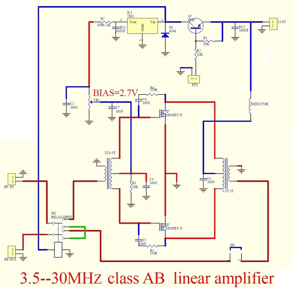
Adjust the biasing
Careful check and adjust the biasing as follows:
- Connect the amplifier to a 50 ohm dummy load
- Using a current limited power supply, apply 13.8V to the board.
- Adjust VR1 to have 2.7V across C7
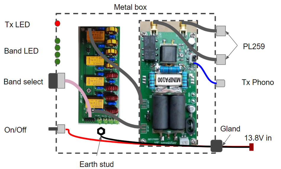
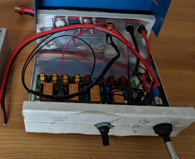
Make the box
I covered the enclosure with masking tape to protect it while drilling and cutting. The holes we're marked out, drilled and de-bured as needed.
The hardest job was cutting the aperture for the main PCB so it can sit on the heatsink through the lid of the box. The outline of the heat sink aperture was drilled out, then the rough edges carefully filled to shape.
When all the components are fitted to the enclosure the amplifier is ready for wiring.
Heatsink tip: Don't drill all the way through the base of the heat sink into the veins. It looks awful and will snap your drill. Use shorter holes and screws or a heatsink with a deeper base.
The amplifier board was mounted through the lid of the box. The hole for the amplifier board was cut out by drilling out the basic square shape with multiple holes, then filing to size.


Always test for shorts before switching on!
I connected the amp to a 50 Ohm dummy load and my FT817. I applied 13.8V and switched on....
It worked.......(for about a minute)! Then it got hot and went pop! When I took it apart I found a small piece of braid lying on the PCB, maybe this was the cause? A replacement power transistor was ordered, I replaced the faulty part and tried it again.
Using the amplifier - Keep the input power low, very low!
Do not connect this amplifier directly to a 5 Watt radio right away, 3 Watts should be the maximum delivering around 50 Watts output, you'll blow it up if you go straight up to 5W. Start with a 1 Watt and work up from there. This will protect your amplifier from SWR issues and high input spikes.
Connected to my FT817 the amplifier works very well. I was able to control the power via the FT817 output as expected. I obtained a maximum power of about 70 Watts from the amplifier which seemed fine for initial testing.
I then progressed to live data modes and made a number of contacts. The amplifier would get hot on the higher power settings, but at lower setting, I found this not to be such a problem (maybe a small fan is needed?).
I then managed a couple contacts SSB on 20 Metres with no complaints.
I'll now refine the setup and continue to test....
Finishing off
The fascia was printed on sticker paper using a regular inkjet printer. Easy. All the important I/O was marked up to prevent errors in the future.
I think it looks great, I'm very happy with the results.
Now for some negatives...
The amplifier works, it's great fun to build. However, the lack of SWR protection turned out to be an issue when trying to squeeze out the higher power. Although the amplifier can withstand an SWR of 2:1, I still managed to blow up the power transistor a number of times. The use of automatic antenna tuner initially caused me problems, just running through the tuning cycle was enough to make the FET go pop.
Keeping that input power down will save the day and allow the amplifier to work well.
Next I need to identify a way to incorporate some SWR protection when I work this out I will post this here.
Keeping the I/P power low is key to protecting this amplifier, although the temptation is always to push it up.
Ideas for amplifier protection....I've not done these yet
Here are some ideas sent to me by Vanni I8JJB to protect and improve this amplifier (thank you Vanni):
Reverse voltage protection
- Add a diode across the FET to protect it from reverse supply voltages
Input attenuator
- Add a switchable I/P attenuator to help protect the amp from high I/P power
SWR protection
- Build an SWR bridge. Use this to switch off the FET Bias power via a transistor and relay arrangement
Improve robustness
- Swap the FET for the higher rated a MRF9180 or SRF8P18261HS
I haven't tried these protection ideas myself yet, but will do at some point in the future. When I'm done I'll let you know!
Return to the QSO Shack Homepage.


