
Make a WSPR beacon from a QRP-Labs Ultimate3S kit
Using WSJTX to test your antenna system with your main rig and a PC is relatively easy, we've documented how to do this here: WSPRX. But you many not want to tie up your transmitter for this task, particularly if you want to run a test over a log period of time.
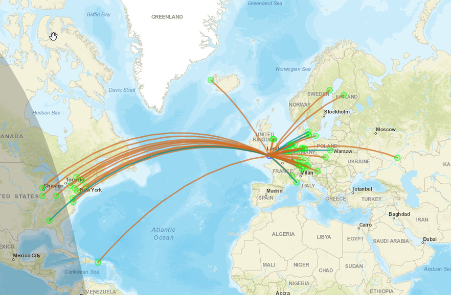
QRP Labs sells the Ultimate3S which is a self contained multi-band and multi-mode beacon kit. Just connect the U3S to your antenna and switch it on, the beacon will then transmit regular digital mode message on the bands of your choice. These transmissions are picked up by other Hams around the world and reported on the WSPRnet website: http://wsprnet.org/drupal/wsprnet/map
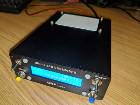
This US3 beacon can be left running continually, it's perfect for testing antenna systems over time. It is highly configurable to suite your own needs (like adding multiple antenna connections for example).A receiver and amplifier options are also available to complement this kit. For more info go to: QRP Labs.
I have really enjoyed making and operating this kit. When completed, the Ultimate3S is a robust, useful and good looking addition to the shack.
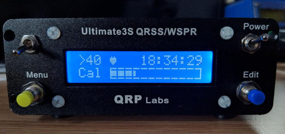
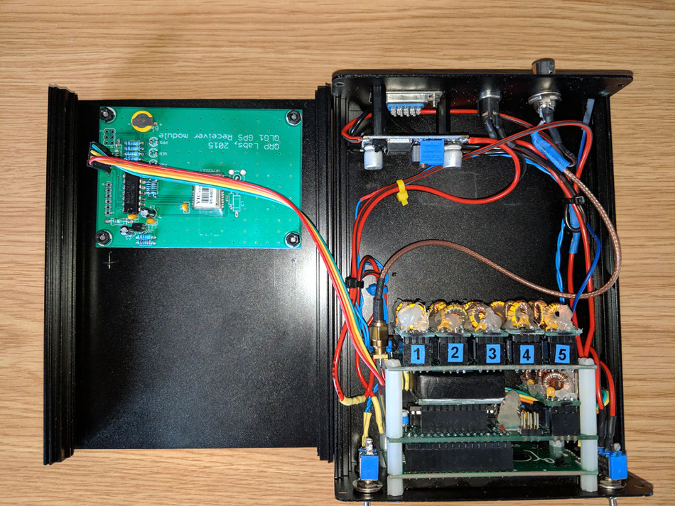
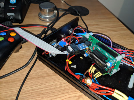
The Ultimate3S kit
There are no surface-mount components, the assembly is straight forward. However, care is needed during the build as there is little room for error. Components will need to be soldered to the PCB's, terroids will need to be wound. The final configuration can be a little tricky, for example: Plugs can be connected the wrong way round, it's easy to apply 12v and damage critical parts! With care issues can be avoided. If you do make an error then fixing problems can be tricky.
It took me over four months to get this kit working correctly (because I made mistakes), the basic unit could be completed in a day if you're careful and good at these things.
The instructions that come with the kit are excellent and need no further explanation. Below I've made some notes on how to avoid potential pitfalls and improve your building enjoyment of this great kit.
Building the UltimateS3 U3S kit
Assembly mistakes to avoid
Here is a list of the mistakes I made whilst building this kit:
- Applied too much power and blew up the micro controller and GPS board (can be fixed, see sections below)
- Connected the U3S main connector 180 degrees the wrong way round, blew up the micro controller
- Connected the power the wrong way round
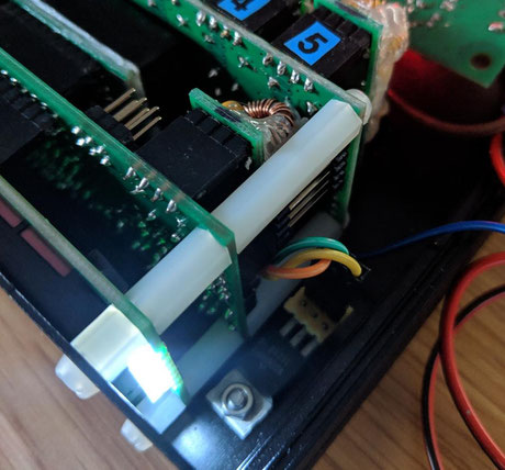
- Didn't fit a LPF to location #1 of the relay board, so no Tx output
- Missed some of the links on the relay board
- Did't set the frequency as it says to do it in the manual (1.4kH higher than WSPR frequency)
- Soldered a bunch of header pins to the wrong side of the board
Tip: Don't make these mistakes!
Protect your U3S from the start
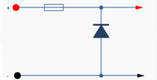
Plan to fit a protect ion diode across your incoming power socket and add a fuse to your supply cable from the start of your project.
The diode should be fitted so it will conduct if power is applied the wrong way round, blowing the fuse before anything else goes pop.
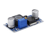
5 Volt supply for your U3S
The Ultimate3S requires a 5V supply. Exceeding this may blow up the GPS board and processor. There is no forgiveness, so be very careful!
To get a regulated 5V supply I used a variable regulator module purchased from ebay. This module is able to step down a 12V supply to a smooth 5v:
- LM2596 DC-DC Switch Adjustable Buck Regulator Converter 3V-40V
This device regulates the voltage regardless of the input voltage, so it will protect your U3S. It will also provide a nice stable supply.
Note: You may need to turn the adjuster screw many times to achieve 5V
Glue your LPF torroids in place using hot-melt glue!
The the Low Pass Filter filter boards are tricky to make and they're easily damaged when handling. To avoid damage, use hot melt glue to secure them in place after testing.
Use header pins, sockets, and labels
Connectors
It's easier to use header pins and sockets to connect this kit up, soldering wires directly to the board can make things difficult during future testing and modification. Boxes of header pins and sockets are easily available from Amazon and are handy to have around the shack.
Error proofing
It's easy to connect things the wrong way round, or plug things in the wrong slot:
- Label plugs and sockets.
- Mark LPF's with their band
- Mark connector orientation with paint (i.e blob of red/green paint on one side of a connector)
- Make connections to a good standard, pull test connections to ensure they are robust
Protect the Si5351A from heat to reduce drift
The enemy of those WSPR spots is drift. As soon as your Q3S starts to transmit, it'll heat up the crystal and you will get drift, this could stop you from logging any WSPR spots. So this is important.
There are two ways around this:
- Buy the OCXO/Si5351A
- Protect your Si5351A from heat.
Protecting your Si5351A from heat is well documented on the QRP Labs website, but it not obvious and can be missed. This is what I did:
Add a heat sink
To protect your Si5351A from heat you can glue a lump of metal to the crystal to slow and absorb any temperature variations.
Add a heat box
I also built a box around my Si5351A using thick plastic card to make a small box. This worked very well.
Either way, solving heat related drift is going to be required for those WSPR modes, so you'll need to address this right away.
Fit the programming pins during your UltimateS3 build
If you fit the programming pins during initial assembly you'll be able to flash your own micro controller very quickly should you ever need to do this. Much easier than having to add the pins later on.
I've included instructions on how to flash the AT328P below.
Flash you own ATMega 328P
I did damage a couple of the micro controllers when setting up the U3S. It is far easier and cheaper to flash you own replacements, here's how to do it:
What you'll need
The following hardware is required to flash your own Ultimate3S micro controllers:
- AVR USBASP programming lead (with six pin connector)
- A pack of ATMega 328P's
- A copy of the latest firmware - from the QRP-Labs website
Install the AVR programming software and driver
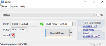
Install the AVR programming lead driver
1) Install the usbasp driver for the AVR programming lead: https://zadig.akeo.ie/
2) Select the USBASP device, then install the lbsub driver
Install AVR dude
1) Install AVRdude: http://www.ladyada.net/learn/avr/setup-win.html
2) Here is the manual: http://www.ladyada.net/learn/avr/avrdude.html
Flash the U3S micro controller chip
Flash a new ATMEGA328p
avrdude -B10 -c usbasp -p m328p -U flash:w:v3.12a.hex
avrdude -B10 -c usbasp -p m328p -U lfuse:w:0xF7:m
avrdude -B10 -c usbasp -p m328p -U hfuse:w:0xDF:m
avrdude -B10 -c usbasp -p m328p -U efuse:w:0x04:m
You should see the script run and program the Atmega328p chip
If you see an error, the check your settings and try again!
Repair the QLG1 GPS board after too much voltage
Simply replace the 14 pin chip, the GPS chip and other components will probably be okay:
- IC1 74ACT08, 14-pin DIP chip
To remove this you'll need a solder sucker pump. The IC and pump can be purchased from Amazon or eBay. If you don't fancy doing this then use an alternative GPS as shown in the next section.
What to change after reverse polarity power to your U3S
You will need to replace the power transistors if you apply voltage the wrong way round to the U3.
Re-flash the firmware.
Setting up the Ultimate3S for WSPR
Here are the U3S settings I used to get my first 20m, 40m and 80m WSPR spots.
Note: You will always need your highest frequency LPF fitted in slot 1!
Physical setup:
- LPF 1 10m *** This LPF must be fitted, this must be the highest frequency***
- LPF 2 15m
- LPF 3 20m
- LPF 4 30m
- LPF 5 40m
- LPF 0 80m - Located on main PCB
- GPS fitted - QRP labs
U3S settings:
- 1]: 0 003,570,100 WSPR 23 1 - Relay 0, 80 metres
- 2]: 3 014,097,100 WSPR 23 1 - Relay 3, 20 metres
- 3]: 5 007,040,100 WSPR 23 1 - Relay 5, 40 metres
- Message: 73 DE #CS
- Call: [your call sign]
- Locator: [set by GPS]
- (Frame Start): 14 00
- GPS (mode Baud): 2 009,600
- GPS: 0 01
- Cal: 01 120
- Park: 1 000,001,600
- Time: [set by GPS]
- XW=0 x2=0 Tn=0 Iv=0 TxS=2
Note: All other settings can be left as they are.
If all is okay you will instantly receive spots following your first TX cycle.
Give your U3S some boots by adding a power transistor
The regular BS170 transistor provides enough power to get lots of spots. But you made need a little more power, maybe to test a Mag loop or compromised antenna.
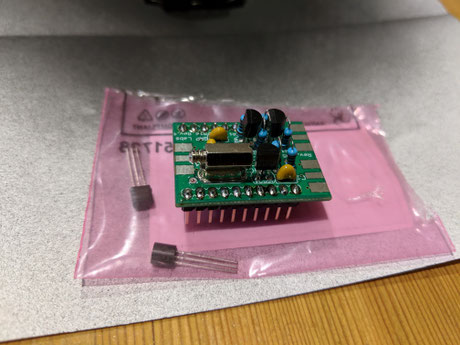
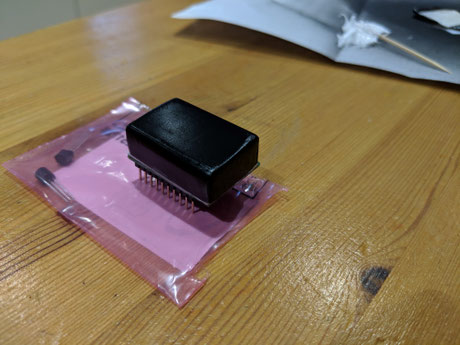
The QRP-Labs Amplifier is the best way to go, but there are other options. You can swap the BS170 transistors with a power transistor (Mitsubishi RD06HHF1) which can be bolted to the chassis, eliminating the need for heat sinks three matched transistors.
The power transistor simply replaces the BS170 transistor as a direct swap, it will need to be located in a suitable place and connected by wires to the original transistor holes:
- Mitsubishi RD06HHF1 RF Power Mosfet
The base current can be set higher when using the power transistor, I set mine to 90mA (60mA + Quesent current). I was easily able to achieve a couple of Watts of power, enough to trigger my ATU.
I was able to turn the power up further but have stuck with the 90mA. Finding how far this can go will require some experimentation. I was happy with the 2 watts output.
Add a receiver to your U3S
I purchased two receiver kits but was unable to get either of them to work. After many hours of debugging, desoldering, and checking, I eventually gave up on the receiver project as it was just making me miserable.
However, I did get a raspberry pi working with WSJTX and an external sound card, so it would have been good if the receiver kits had worked.
Return to the QSO Shack Homepage.