
Digital SWR meter kit
Understanding your antenna SWR is important to all radio operators. Making an SWR meter from a kit is fun!
This page documents my experience of building the digital SWR meter kit purchased from http://www.radio-kits.co.uk/swr_meter/
The kit of parts
I purchased the recommended enclosure with the kit from the radio kits website. Ordering was simple and straightforward. The kit arrived quickly via standard mail. All the parts were well packed and easily identifiable. ESD packaging was used where required.

Preparing for the build
Two PL259 patch leads were purchased from Amazon to connect the SWR meter to my radio and antenna tuner upon completion. A 9v battery and some wire were also required to complete the build. To avoid ESD issues all electronic work was conducted on an ESD protected mat. Solder, soldering iron, wire cutters files drills and screwdrivers were also needed.
Populating the PCB
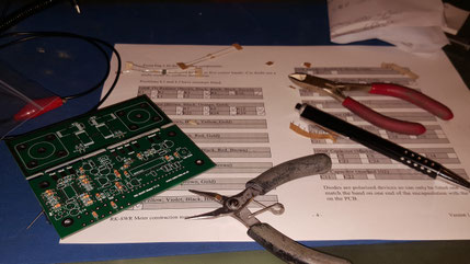
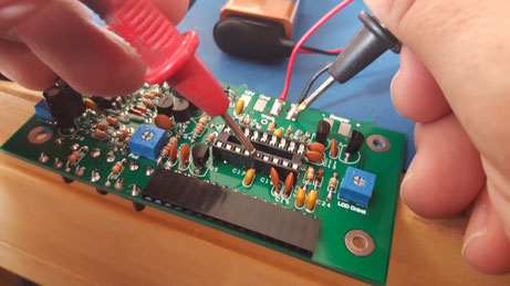
The components are placed as per the instruction. Only a few components should be placed before soldering as they are quite close together on the board.
Component identification can be a problem. I found the use of a mobile phone camera to be beneficial.
Rather than trying to fit the components in any particular order, I decided just to pull out a part, identify it and fitting it. For me, this worked best. My son worked with me to fit the parts which were a great help.
Soldering was straight forward, although I could have done with some finer wire cutters to help with the cropping of the legs. Also, ticking off the fitted components on the instructions is essential.
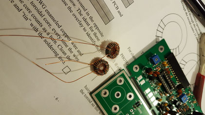
Winding the coils was straightforward enough. I unwound about 10 inches of wire and wound this around the toroidal ring. Being careful to avoid kinks this all worked out OK. I counted the turns using a mobile phone camera as the number of turns is critical to the performance of the SWR meter.
At this point, I would recommend getting access to a solder sucker or solder braid. It was very easy to accidentally plug a PCB hole with solder, when this happens you will need a way to clear the holes so the component can be fitted. I did actually manage to fit a transistor the wrong way round, solder braid was required both to remove the transistor and refit it.
Testing before connecting the screen and processor
When all the parts and components are fitted to the main PCB it's time to power up and check the 5v rail, this is done before connecting the screen and processor chip.
The 9V battery connector is soldered to the board. Then the 'on' tact button is pressed while measuring the voltage on pin 14 of the main processor socket. When I first did this, I found that I only had 2v on the rail. I checked all the solder joints, resistors and other components (which was a lot quicker than I expected). The problem was that the 8 pin chip was fitted the wrong way round. I carefully de-soldered the device using solder braid and refitted. I was rewarded by the 5v being present on the rail. All good.
Fitting the screen and switching on!
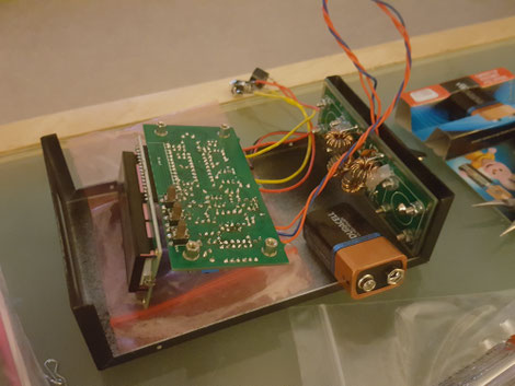
Next, the processor chip, screen, and rear connector board are fitted. Some wire will be required to do this, so it's important to make sure this is ready before the build. When I switched the unit on for the first time I was presented with a blank screen. Following the instructions, I adjusted the pots and backlight settings so I could see the displayed text.
Calibration was simple enough and involved connecting the rear sensor board wires to a 9V reference pin on the board. I then connected the un-boxed unit to my radio and was rewarded by the power and SWR being displayed as expected.
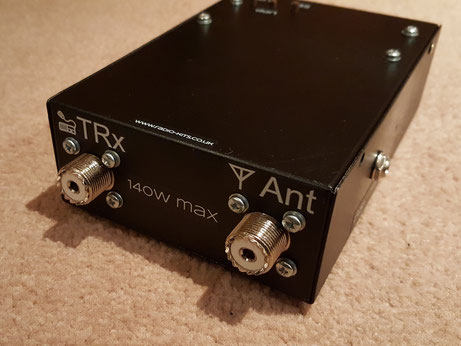
Tip: Take note of the TRx and Antenna connectors, this is written on the board but can be difficult to see when the board is fitted.
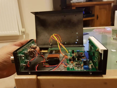
The enclosure
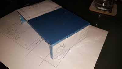
The first thing to note here is that the main PCB and push buttons will hang down from the top of the enclosure. To ensure that the screen could be supported I decided to turn the enclosure over so that the screws were at the top.
I printed and fitted the supplied cutting templates using clear tape. All holes were centre punched before being carefully drilled.
Note: The templates did not work out as well as I had hoped, a number of last-minute adjustments were required to make things fit. I recommend using the templates as a guide only, check your measurements and be sure yourself before drilling!
A high standard circular hole cutting saw was used to make the two 16mm holes in the rear panel. All other holes were started with a 1.5mm pilot drill and were finished off with the final size drill bit. Holes were de-burred using a small round needle file.
The square display hole was cut as suggested in the instructions. Multiple holes were drilled and large wire cutters were used to remove the centrepiece. A square and flat file were used to finish the hole off. With a bit of care, I was very pleased with the results.
The plain aluminum case was painted satin black using BBQ paint. This paint is fantastic for this type of project, it always gives a great finish and requires no primer.
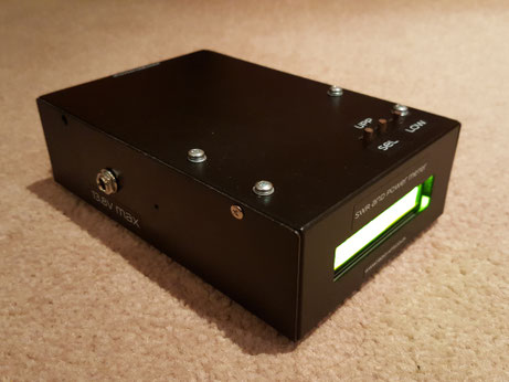
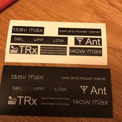
Finishing touches and using the unit
To finish the unit off I purchased a fantastic sticker set from a decal vendor. The stickers really brought the unit to life and made it look like a purchased item. Four sticky feet were added to the base and the Digital SWR meter was finished.
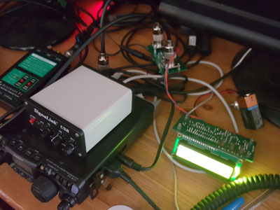
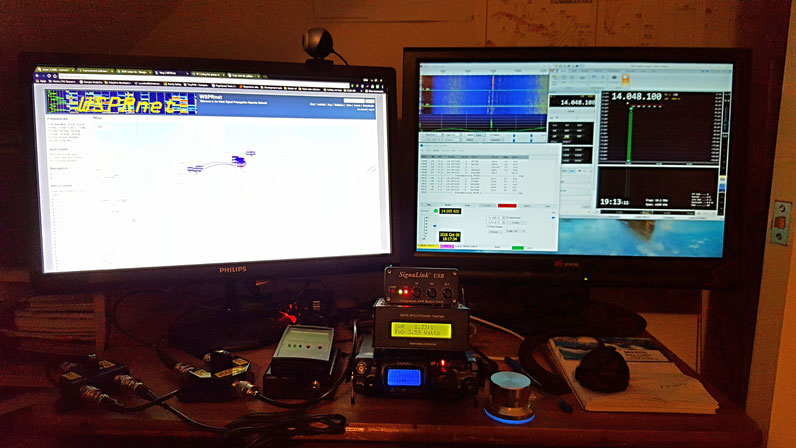
The unit sits nicely on top of my FT817 and looks smashing. The battery appears to go on and on so I have not tried connecting it to a mains powered PSU just yet.
A nice feature is that the unit will start up on transmit automatically, it just works great.
I'm very happy with the meter, it performs exactly as expected and looks great. It is so useful I just don't know how I got along without it.
Return to the QSO Shack Homepage.