
Make a tri-band satellite antenna array
Venturing into the UHF/VHF, and even the GHz bands can open up a whole new world to this hobby. When you add a rotating beam Yagi array to your VHF/UHF rig things can get really exciting. Satellite repeaters, satellite data download, Tropospheric DX, and even talking to astronauts on the ISS are all possible.
But just how do you go about getting hold of a rotating antenna array? You can't buy them. So they have to be made. How should they be configured? What cable to use? What about the rotor?
On this page I will share my experience of constructing and erecting an tri-band antenna array for satellite and long range amateur radio operation.
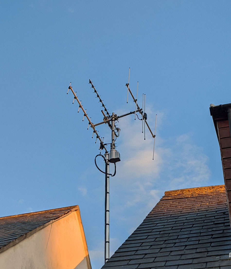
Tri-band satellite antenna configuration: Polarisation, angle and size
Best satellite antenna polarization
There appears to be no clear guidance on this, other than it's important. I used vertical polarisation for the 2m and 70cm Yagis. The 1.2 gHz is horizontally polarised. The rational for this layout was 'ease of build'. Other configurations appeared harder to construct, or can consume more space. This polarisation appears to work fine.
If anybody has better advice then send me an email and I will update this page accordingly.
Ideal satellite antenna angle
Internet research appears to suggest the ideal configuration of the satellite antenna array is to point the Yagi antennas 10-15 degrees upwards.This allows for maximum gain across the horizon, while achieving maximising gain into the sky. During my satellite work I've noticed that they spend most of their time hovering around this point in the sky, so 12.5 degrees appears perfect.
Size, sweep and space: Rotating tri-band antenna
Bigger antennas put more strain on the rotor, can be harder to install, and consume more room. Longer Yagi antennas increases gain, but reduces gain spread. You'll need to be careful not to swing over somebody property with your antenna. Choose antenna size carefully.
My 3 element 2 meter Yagi, is not too long, but provides great results.
When mounting I kept everything a wave length apart and configured the frame to keep everything balanced.

Only a plonker would ignore basic safety
It's very important to understand the safety parameters of your antenna system. You can injure yourself, and do others harm if you ignore these things. So make sure you keep on top of these things, a key consideration is safe antenna distance. I'd recommend this page for this purpose:
What you'll need to make a rotating tri-band HAM SAT satellite antenna
Here's the shopping list for my HAM SAT array:
- RCA antenna rotor
- 2" aluminium antenna pole
- Universal antenna bracket x 2
- Right angle antenna pole
- 2m Yagi
- 70cm Yagi
- 1.2 gHz Yagi
- Ultraflex 7, low loss coax
- Correct, grommet connectors for the Ultra-flex 7 coax
- 5 or 3 core Rotor cable
- Ground wire (for grounding)
- Cable ties
- Self amalgamating tape
Assembly - How to bolt it together
The finished article is going to be big and cumbersome when on the ground, it can be easily damaged if not handled correctly. I found that it was easier to make it up outside of the house. The use of patio furniture made an excellent construction stand.
Basic satellite antenna construction
To achieve the vertical angle, a horizontal pole is used to mount the 2m and 70cm Yagi antennas. The vertical pole is fixed using a Universal antenna bracket.
The 1.2 GHz antenna is fitted to a Right angle antenna pole, again secured with a universal bracket.
To cut the tubing I used a plumbers pipe cutter, maybe a hack saw and file could also be used?


Wiring up before installing
All cables need to be fitted prior to final installation. The downside is that this makes the antenna heavy due to all that copper hanging off of it, so be aware of this.
I made up the leads to the required length. Suitable weather proof connector were fitted (no scrimping on this as any repairs will be difficult in the future).
Each cable was fitted it's antenna, and sealed using self amalgamating tape. Then each cable was carefully routed down the antenna array to just above the rotor motor.
Check for shorts: At this point it is very important to use a multi meter to check for shorts. It may sound obvious, but just one stray strand of braid in the connector at this point may cause an expensive disaster later on. Take the time to check.
Clearly label: Mark each of your leads as needed. Make sure your marking method is robust. I used blobs of paint, lots of them. But after threading these through walls etc. The blobs of paint were only just viable. So again, do this with thought and care.
Cable selection: At these higher frequencies the losses in the feeder line are much greater. You should use low loss coax if possible, but also do remember that the feeder needs to be flexible to accommodate the rotor. I used: Ultraflex 7, low loss coax
RCA VH226F antenna rotor
I used a lower cost RCA VH226F antenna rotor. This rotor works absolutely fine for this type of antenna. No problems at all.
To reduce stress on the rotor, the antenna array should be balanced and as close to the rotor as possible.
Important: Set the antenna rotor to Zero degrees before fitting!
Alignment before fitting is important
Setting the antenna rotor to the correct start position is very important, or your display will not show the correct direction when you eventually use it.
Power the unit up and set it to the initial position, by pressing initial. This will place the rotor in the zero degree position.
Connecting up the RCA rotor
Connect up the rotor wires before fitting. Make a very careful note of which wire goes where. I took a photo and emailed it to myself as a backup.
Other preparations
I made sure the cables were very secure. On the internet somebody suggested that adding Locktite to the internal bolts to stop them from coming loose, this looked like a good idea so I did this.

Grounding the antenna frame
The instructions for the rotor and the Yagi antennas all said that the mounting brackets must be grounded. The rotor instructions said that the base pole was the correct pace to do this. So I connected some heavy gauge car battery cable from the antenna pole mounts directly to an earth spike buried in the ground.
Aligning and installing the antenna array
I used a professional antenna installer to fit the antenna to the side of my house. They mounted the antenna array on the top of a heavy gauge aluminium pole. Three mounting brackets and some heavy bolts were used to fix these to the side of my house.
Also, care should be taken to avoid bending the antenna, if it does get bent, then get the installer to fix this when they are up there.
Once it was up the installer routed all four cables into my shack, the earth lead went directly to the ground.
Alignment of antenna when fitting
The antenna must be positioned to point north. Regardless of the rotor fitting position, the antenna must point north.

Using the antenna
This antenna system works great for me. I've had no problems with this at all.
Using the digital RCA rotor controller is very easy for satellite work. Easier than I through it was going to be. The rotor controller tracks the antenna position perfectly as far as I can tell. You do need to leave it switched on or it losses it's initial position, or it can be set back to zero degrees before switching off. Other than that it's perfect.
Works great with my IC-9700, a huge amount of fun and lots of new things to learn. A highly recommend project.


Return to the QSO Shack Homepage.