
Make a simple band selector interface for your FDM-Duo radio
Decode the IC2 serial data from the FDM-Duo in to FT817 band voltages

On this page I'll cover how to make a ELAD FDM-Duo to Hardrock50 band data interface. This is a tricky project due to the surface mount DAC5571, so I would recommend buying an interface from the HobbyPCB website if you hate surface mount components and/or soldering. The HobbyPCB products are excellent, their interface is plug and play, ready to go off the shelf. Save yourself the trouble and buy one.
However, if you like making things, then below I will share with you how to make an interface using the DAC5571 DAC chip.
The information to do this was found in the ELAD FDM-Duo manual, the HR50 manual, the ELAD FDM- DUO forum, along with some other internet sources.
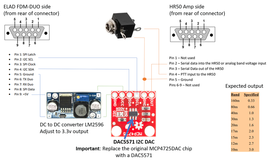
Duo to HR50 band control interface strategy
This interface is intended to work in the same way as the official interface that can be purchased from the HobbyPCB website. I just like the challenge of understanding how this works and making one myself.
The interface is supposed to read the IC2 data from the FDM-DUO serial data port via a DAC5571 (digital to analogue converter), this then outputs the correct voltage to switch bands, just like the output from an Yasue FT817.
A PTT connection is provided from the Duo to the HR50 data port via a 3.5 mm audio jack socket.
Why not use the MCP4725?
The MCP4725 appears not to work, but the PCB's that these can often come on are useful. My plan is to remove the original MCP4725 and replace this with a DAC5571. This was recommended on the ELAD DUO forum.
But, the cheap DAC module does come with a very convenient PCB equipped with all the I/O, biasing resistors etc.
Fitting the new DAC5571 to the board
I removed the original DAC by heating all three pins on one side, then lifting that side to disconnect the pins. Simply repeat on the other side, and the DAC will fall off.
To fit the new DAC5571, I use a very small piece of Bluetak to hold it in place. I then carefully aligned the pins before soldering. Where there was too much solder, solder wick was used to remove this.
I buzzed out all the pins, and checked for shorts, when all was good I proceeded to connected it up to the d-type connector.
Boxing up the band control interface

I simply used a small plastic box with just enough room to mount the two d-type male connectors, stereo jack socket, and PCB's. Hot melt glue was used to secure the PCB's. Wiring up was simple.
PTT jack socket
The PTT connection is made to the tip of the 3.5 jack lead only. The ring is not connected.
Voltage adjustment
Before connecting to the radio I buzzed the interface out for shorts etc. Once I was happy, I connected the interface to the radio and set the voltage trimmer to give me 3.3 volts exactly.
Labeling
Because both ends of the interface are identical, it was important to label each end.
Switching on
HR50 settings
The HR50 is set to FT817 interface mode. PTT is set to PTT.
Connections
9-pin RS232 m/f leads are used to connect the interface box to the Duo/HR50. The PTT is connection is made between the Duo radio and the interface box using a stereo jack lead.
Warning: Set you O/P power of the Duo to 0.5 Watts before connecting. 1.5 Watts is enough to achieve 50 Watts from the HR50.
It works!
It works just fine. Perfect!
Adding Bluetooth compatibility
It would be easy to add a TX/RX HC-05 board to this interface to allow for BlueDuo compatibility. Details on how to add a Bluetooth module and more on the BlueDuo software can be found here: https://hamradioscience.com/wireless-touch-screen-remote-for-the-elad-fdm-duo/
Program the HC-05 using an Arduino, it's easier than a RSP
I used this guide to initially setup the HC-05 ready for programming: https://exploreembedded.com/wiki/Setting_up_Bluetooth_HC-05_with_Arduino
Commands to send to the HC-O5
- AT+VERSION
- AT+NAME=BLUEDUO
- AT+UART=115200,0,0
- AT+PSWD=1234
Coming soon!