
Improve your Bitx40 with these simple upgrades

For me, making the Bitx40 has been a huge amount of fun. I've nurtured it from a basic SSB radio into an effective 40 metre digital mode rig. Each modification makes the radio a little better, each contact gets a bit more satisfying.
Out of the box it's not the most refined radio you will use, but it does work. The basic radio can be improved, modified and upgraded. There are plenty of resources on-line to cover most things, many of these mods are relatively easy to do. Each enhancement making the radio a little bit more capable, it appears there are always more features and upgrades that can be added.
When I mention my Bitx40, I'm often asked 'so what have you done to it?'. To help me answer this question I thought I'd share the modification I've made on this web-page. I've listed all the useful modifications that have been made to my Bitx40 radio below.
I hope you find this page useful, maybe it will help improve your experience of this little radio as well.
What is a Bitx40?

The Bitx40 is a 40m 7 watt transceiver kit purchased from India. It is an open source design made into a kit by HF-Signals. Everything is provided in the kit to make a fully functioning transceiver (a speaker or headphones must be sourced separately).
The transceiver kit is minimal out of the box. With the use of a purpose made case and a couple of simple mods this kit can turned into a fun radio for your shack.
You can buy the basic Bitx40 kit from here:
Recommended modifications to improve the Bitx40
Below is a list of the modification I've made to my radio. All have been successful implemented on my own Bitx40 radio.
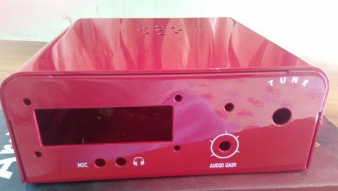
Metal case to house your Bitx40 radio
You can buy this smart metal case from here:
Its a solid metal enclosure which looks great and has enough space for your modifications and wiring. Pre-cut holes, painted and screen printed, a great place to start your project.This case could save you a lot of time and effort if making enclosures is not your thing.
Also, these cases come with a speaker, pots, screws and connectors. Everything you'll need to complete your Bitx40 is included. Okay, you may need some wire for the power cable, but the plug is included with this case!
Tip: I used the 'Universal Case Blue II For Bitx40' as seen in the images on this web site.
Connect up the Bitx40 microphone socket like a KX3!
Why? Because these connections are logical, available and easy to achieve.
I had an Elecraft compatible microphone knocking around which I knew worked well, so this was the most logical connection method for me.
By using the Elecraft KX3 connections I ended up with a dedicated headphone socket, and a dedicated microphone and PTT socket. This also made connecting the Bitx40 to a sound card (for data modes) simple as there are many solutions for this radio sound card combination.
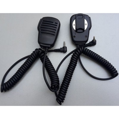
Low cost microphone
There are low cost KX3 compatible microphones available, if you can't find one then buy a cheap fist microphone and rewire it to suite the pinning below.
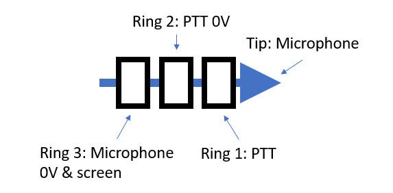
Microphone socket pinning
- Tip = Microphone
- Ring 1 = PTT
- Ring 2 = PTT 0V
- Base = Microphone 0V
Microphone jack socket (4 way)
You'll need a four-way 3.5mm jack socket, these are available online.
Firmware, function button, ten turn pot, and more for your Bitx40
All of the above tips will give you a basic working radio. Now to really add some bells and whistles go to this page and add a function button and new menu items!
Here is the reference link:
Essential mods found on this page include:
- Firmware - Menu options and more!
- Function button - Used with the firmware to access menus
- PTT seance - Required to eliminate pops and squeaks!
- Fine tune button - Easy to fit, makes tuning easier
Suggested shopping items:
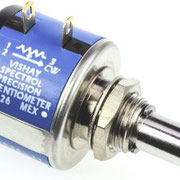
- Ten turn 10K pot (don't buy too cheap!)
- Push buttons, Momentary Latching Mini Push Button Switch
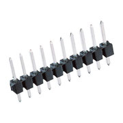
- Header bar
- Header bar connectors
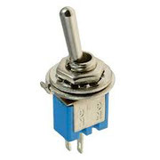
- Mini toggle switch (for fine tune mode)
Important: Follow the firmware setting steps after installing the firmware!
Tip: Use a header pin to make the PTT seance connection (so you can disconnect the board)
Tip: Set the ten turn pot to cover half the band only. This makes tuning a breeze and is much nicer to use.


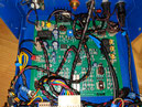
Bitx40 RF gain control to clean up the signal

If you want to turn down all that QRM noise, then this feature will be high up on your to-do list. An RF gain control can be added with the use of a 1K pot connected in series with the RF track.This mod actually adds an attenuator to the RF input of the receiver.
You'll need a two pin header, some screened cable and a header connector.
The RF track is broken on the PCB and a header is attached to the board (as shown on the left), a 1K pot is connected to the new header via screened cable to complete the circuit.
Here is the reference link:
Tip: I glued the header to the board using epoxy glue. Super glue does not work.
Tip: Use 50 Ohm coax to make the connections to the potentiometer.
Get rid of the Bitx40 hiss with a feedback loop
The basic Bitx40 kit comes with a lot of audio hiss. It's darn annoying. For me, this mod is essential. Removing the hiss and improving the audio quality totally transforms the radio.
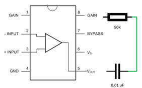
You'll need to add a 0.01uF capacitor and 50k resistor to the LM386 amplifier (across pins 5 & 8).
It's the only 8 pin device on the board.
Here is the reference link:
Tip: The official instructions suggest a 10K resistor. For me, this made the audio response too flat. After experimentation I settled for a 50K resistor which provided a nice crisp sound for my setup.

Add a better Bitx40 speaker for a rich, warm sound
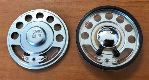
Once you've implemented all of the above mods, the audio quality can still be improved by adding a better speaker. The speaker that comes with the case is alright, but its only just acceptable.
Replace it with a 57 mm Mylar speaker (4W, 8 ohm), the same type that is used in the FT817 would be perfect!
This will provide warm and clear audio, and another significant step up in performance.
Tip: Make sure the speaker is securely fitted to the lid of the case. The clips that come with the case should be fine.
Use a clean 12V supply to reduce noise on your Bitx40
I've found that the 12V supply needs to be very clean for the Bix40 to keep the noise down. Even my FT817 PSU is too noisy, any supply noise is transposed directly to the audio if no suppression is added. Either use a battery supply or add a 12V EMI filter to solve this problem.
A filter can be easily made, alternatively you can buy a pre-made filter from eBay for $2. All incoming power should go through the filter. However you do it, a clean supply is a must!

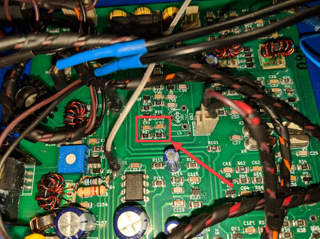
Enable Bitx40 Upper side band (USB) by removing two capacitors
To get the upper side band working, you'll need to remove C91 and C92 along with the firmware and function button mod (described above). This modification is required to access data modes.
Don't worry, these capacitors are redundant, they relate to the original on-board VFO. I've pointed them out on the image to the right.
Removing the capacitors is relatively easy. I used solder braid to suck away the solder, the capacitors simply lifted away.
Keep them for future use if you like.
Tip: You will have to set the USB offset through the menu items, set the LSB offset first.
Add some suppression to the Raduino board to further reduce noise
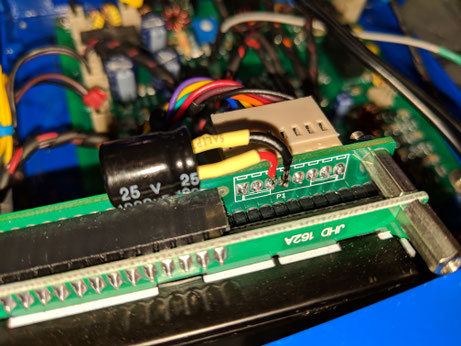
You can add an electrolytic capacitor directly to the Raduino board to potentially reduce further noise.
I added one the the back of the Raduino power connector as shown on the left.
I'm not sure how much of an effect this has, but other people have done it and I'm happy with the lower level of noise on my Bitx40.
Data modes on the Bitx40
With the above USB modification and the KX3 microphone pinning, you'll be able to use data modes. The BitX40 is really good at doing this.
You will need to set the LSB and USB offsets carefully, but once done you'll be very happy with the results.
You will need to manually select the data mode frequency, other than that it will work just fine.
Follow these KX3 data mode instructions to get started: https://www.qsoshack.com/data-mode-communication-on-the-elecraft-kx3/
WSPR plot for my BitX40
I left my Bitx40 running for a day under the control of WSJT-X. Transmitting on about 4 watts, here are the results:
To find out more about using WSJT-X, follow this link: https://www.qsoshack.com/wsjt-x-quick-start-guide/

Add a QRPlabs VFO to your Bitx40
The QRP labs VFO offers a rotary encoder, automatic GPS calibration and multiband control options. It works great, and sounds great! The VFO upgrade kit is available from here:
- https://qrp-labs.com/vfo.html

Use a 5v power supply for the QRPlabs VFO
Firstly, you'll need a 5v PSU. I did by using a simple DC-DC Converter board purchased from the internet ($6 for three!). As you can see in the image these can be bolted to the back of the VFO at an angle using plastic stand offs.
Important: Set the correct output voltage before connecting power to the VFO. You'll damage the VFO if you apply too much power.
Connect the Clk0 output to the Bitx40
Once the VFO is powered up and working simply connect the Clk0 output to the DDS1 input on the Bitx40 board.
Tip: I used screened cable for this which made things much quieter.
Set the VFO offset correctly
For the Bitx40 you'll need to set the IF offset.
- VFO IF offset '-12,000,000'
An explanation for this is included in the VFO instructions.
Replace the Bitx40 BFO with the VFO Ck1 Output

Once the VFO works, then consider replacing the Bitx40 BFO with the QRP labs VFO CLk1 output. This provides sharper clearer audio, also many of the click, pops and crackles will be eliminated by doing this.
- Ck1 BFO frequency setting: 011,998,000
Add the QRP labs GPS board to calibrate the VFO and show you the time!
Add the GPS module for automatic VFO calibration, display coordinates and a clock! I mounted mine inside the case.
There is an issue with the GPS board being so close to the radio, it's noisy. The noise radiates from the entire board, so maybe a grounded metal screen could stop this?
Reduce the QRPlabs GPS noise, you can try this:
- Fit a 1K ohm resistor in series with the data line (TX/RX) between the VFO and GPS to reduce electrical noise from the GPS board.
- Use screened cables for the volume control
However, this will only reduce the noise, and will not eliminate it entirely. So you may want to add a GPS on/off switch so the GPS can be shut off when not needed. This is what I have done.
Fit an AGC board
Sadly, I did not like this mod as it didn't really enhance the radio. I ended up removing the AGC board and refitted the RF gain control pot instead.
If you want to give it a go, then an AGC board can be purchased here: https://shop.kit-projects.com/index.php?route=product/product&product_id=123
Return to the QSO Shack Homepage.